Last year, I wrote a blog about general EFO theory. This edition will focus on the history of the “flame-off” and a few more advanced topics. But first, let’s discuss the evolution of the flame-off system that evolved into electronic flame-off systems that wire (ball) bonders use today.
Flame-Off History
The original Hughes Model 360 was “the Mean Green Machine”, a manual ball bonder that used a hydrogen flame to form the ball. That’s where the acronym “flame-off” comes from, as it was an actual H2 flame that melted the gold wire into a very small ball. Its era was the 1960s; H2 flame-off was typical during this period. The process engineers that used one of these bonders remember them well, as when hydrogen burns it is colorless; many a hand has wandered into the invisible flames’ path for a fraction of a second. H2 burns hot–it has to in order to melt solid gold! It did a fair job at forming the ball with little contamination, but free-air ball size was very difficult to control.
The next flame-off systems were used on the Hughes Model 460 and its era was the 1970s. The 460 ushered in the EFO, or Electronic Flame-Off system. This system later on was dubbed a “Positive EFO”, but in the 1970s no one knew of anything else, so it was simply called EFO.
In the mid-1980s, a new EFO system started showing up on the new automatic bonders, like the Hughes Model 2460-III, -IV, and -V. It was called a “Negative EFO” (NEFO) system; when that technology started to be optioned on the newer bonders, the industry started calling the older systems a positive EFO.
The older Positive EFO units used a lower high voltage system. It hurt a lot less if you ever made the mistake of leaning on the start or stop buttons while threading wire–NEFO would make you grind your teeth! The Negative EFO system more than doubled the high voltage output, but also reduced by more than half the amount of current applied during each ball formation for safety considerations. Multiple safety systems are in place to protect the operator from lethal power settings. Spark direction changes as well with the NEFO.
So why the change? Some said the NEFO made ‘softer’ balls (thus less cratering), others said better energy repeatability and control, and the capillaries were supposed to wear better (last longer) with a NEFO system. We checked all these reasons, and while they seemed valid, the differential was pretty small. The capillary did stop plating carbon after the switch, but it didn’t seem like 2x additional bonds. The smart move is to never run your capillary until it becomes a problem. Watch your bond counters, and replace them on regular intervals.
Ball Bonding and the EFO Process
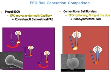
Ball bonding requires precise control of the electronic flame off process. Lack of control affects the FAB (free-air ball size) which affects the final deformed bond size and shape. There are very few controls driving the EFO process. The main driver is the on time of the electronic spark.
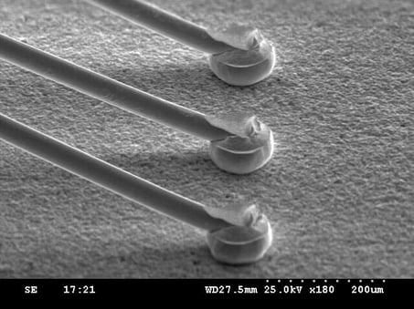
When triggered, the EFO system moves the EFO wand under the wire. A large voltage is applied between the wire and wand, and a spark occurs. As long as power is provided, this spark exists and most look at this as a plasma (heat) that literally melts the wire. Surface tension of the gold wire forms this melted material into a ball. The longer the plasma exists, the larger the Free Air Ball.
Most wire bonders expose a very specific amount of wire, called the tail, to the wand prior to initiating the EFO process. The ball is formed, and it melts up into the capillary chamfer. You need to be a bit careful with this process, as you need to manager the EFO ‘on time’ against the amount of material you have exposed to generate the Free Air Ball. Make the tail too short, or the EFO on time too long, measured in milliseconds, and you melt the ball past the perfect spot in the chamfer of the tool.
Heat Affected Zone
The last concept to share has to do with grain boundary formation in the HAZ (Heat Affected Zone) just above the ball. As the ball melts up into the capillary chamfer, it is a boiling mass of near pure gold. Just above that boiling ball is an area where the wire is partially melted, and the tiny amounts of added materials (dopants) come together as the ball cools and solidifies. This creates a weak area on the wire where destructive pull testing will show to be lower strength than the tensile strength of the wire.
To minimize this affect, we try to increase the temperature of the plasma field, and reduce the time we ‘cook’ the ball. The way we do this is by increasing the spark gap to its maximum. That generates the strongest plasma spark, and by forming the ball faster (in milliseconds) we can effectively minimize (it doesn’t go away) the grain boundary formation. This makes for a stronger wire interconnect. Combine this trick with Stand-Off Stitch bonding and you will see little to no adhesion failures on either end of the ball bonded wire, 90%+ mid-span breaks, and the few fliers will be in the HAZ above the ball.
Stand-Off Stitch Bonding – generates ultra-high reliability interconnects
If you would like to discuss more specifics, contact us here.
| 8000i Wire Bonder/Ball (Stud) Bumper Data Sheet | Improved Wire Bond Relaiability eBook | Improved Wire Bond Reliability Technical Paper |
 |
 |
 |
----
Bradley K. Benton
Western Regional Sales Manager
Palomar Technologies, Inc.