The Palomar Technologies 8000i Wire Bonder/Ball (Stud) Bumper and 9000 Wedge Bonder both have a good selection of wire bonding “loop modes” to accommodate various process situations and achieve various wire loop profiles.
On Palomar wire bonders, these “loop modes” represent the type of wire to be executed. For loop modes that represent two-bond wire types, the loop mode indicates the type of motion profile that will be executed by the real-time controller between the first bond and the second bond. For loop modes that represent single-bond wire types, such as stitch-off and ball bumps (on the 8000i Ball Bonder), the loop mode represents the different approaches to preparing or completing the wire for the single-bond type.
Loop Modes – A Quick History
When the 6000 Ball Bonder (the direct predecessor to the 8000) was developed, the loop modes from the Hughes/Palomar 2460 Ball Bonder were ported over as closely as possible. Those 2460 loop modes themselves represented many years of development and refinement. Porting these loop modes immediately gave a baseline of known useful loop sequences that could be used for machine verification while developing the 6000 Bonder.
The 6000 Ball Bonder was successfully manufactured and sold for many years. During that time, a number of new loop modes were developed and added to the system.
As the original 8000 Ball Bonder was developed, all of the 6000 loop modes were retained. This wasn’t as challenging as the 2460 to 6000 port because a similar real-time controller was being used between the 6000 and 8000 systems. In addition, the Z system mechanics were also very similar between the 6000 and 8000.
To this day, both the 6000 and 8000i systems are fully supported and share the same loop modes. Even though the 6000 system was superseded by the 8000 system many years ago, any existing 6000 system can still be upgraded to the latest bonder software (with a possible BPU upgrade needed) and run all the loop modes developed on the later 8000i system.
The 9000 Wedge Wire Bonder was developed and released within the last few years, but it also benefits from a deep history with some roots in the Hughes/Palomar model 2470 wedge bonder. The 9000 and 2470 are more different from each other than the 2460 and 6000/8000i are from each other, so bringing over wedge wire sequences from the 2470 directly wasn’t feasible. But, the existing 9000 wedge loop modes were influenced by some of the profile behaviors of the 2470.
Process of Loop Mode Development
Each loop mode has an associated unique name and an internal number to differentiate it from other loop modes. In addition, each loop mode has an associated set of loop parameters to control the various aspects of the given loop mode.
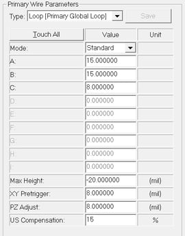 8000i Ball Loop Mode Parameters
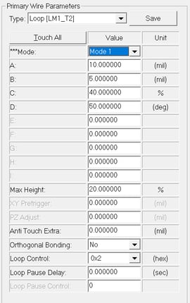 9000 Wedge Loop Mode Parameters
The explicitly named loop parameters such as “XY Pretrigger” on the 8000i bonder or “Anti-Touch Extra” on the 9000 bonder have fixed functions that are shared among all loop modes. The generic loop parameters “A” through “I” are parameters that can change in function from one loop mode to the next. These generic parameters allow for configuring the exact behavior of a wire loop for a given process, giving the customer flexibility without having to devise every single motion themselves.
On occasion, existing loop modes are insufficient to cover an individual customer’s process needs, or are found to not address a newly recognized general process need, such as a new kind of component assembly or geometry. An experienced wire bonding customer may recognize a need and may even propose a loop sequence to address that need. More commonly, Palomar Technologies’ Applications Engineering (AppsE) group will recognize a possible need when using existing loop modes and trying to provide a functional customer solution.
Palomar Technologies’ Software Engineering (SWE) group can get involved in the loop development process at a couple of different levels. If AppsE thinks there may be a behavioral issue with an existing loop mode, or that an existing loop mode could be slightly adapted for a new scenario, then that can be enough for SWE to start work on the implementation.
SWE will verify that the loop mode can be slightly modified to accommodate a newly desired behavior. In that case, the change in behavior must be optional and must be controllable via the generic loop parameters. In this way, original sequence behavior will remain unchanged and new behavior can be optionally used by setting one or more parameters.
AppsE may devise a new loop sequence, perhaps from customer suggestions, or from experience with a single customer or across multiple customer experiences. In this case, a fairly detailed loop sequence will be devised by AppsE with possible SWE involvement if needed. Once the detailed loop sequence is described sufficiently, then SWE can implement the new loop mode. SWE and AppsE will then test the loop mode, with AppsE doing an actual application or by wire bonding on test components. If the loop mode satisfies the performance and test result expectations, it will be committed into the software for release.
When a new loop mode is developed, a new loop name and loop number are set aside to represent it. The loop number will never change and is used as a unique identifier in all loop settings as stored in loop parameter files and in part programs. The loop name is used for display and documentation purposes and will generally never change, although may be modified for clarity or naming convention purposes.
Once a loop mode has been placed into released software and utilized by an end customer, it will be supported in all future software releases. It will remain as unchanged as possible to retain stable performance and behavioral characteristics.
Every existing loop mode is carefully documented, with a description of the loop mode profile, detailed definitions of all loop parameters, recommended applications, and various notes about practical behaviors. Palomar Applications Engineering maintains all loop mode documentation and can provide reference material as needed.
For more information on these machines and capabilities, contact us, or download these resources:
| 8000i Wire Bonder Data Sheet | 9000 Wedge Bonder Data Sheet | 8000i Wire Bonder Frequently Asked Questions eBook |
 |
 |
 |
| 9000 Wedge Bonder Frequently Asked Questions eBook | ||
 |
----
Raul Rathmann
Senior Software Engineer
Palomar Technologies, Inc.