In the third part of this blog series, we outline our technical success in demonstrating the use of jet dispensed silver sintering. As we previously explained in part two of this blog series, the most effective process was only finally secured through the development of Palomar’s propriety Fixed BLT software which we will examine below. First, however, it is important to show what we believe is the superiority of jet dispensing over its principle rivals:
- The time and pressure dispensing method process utilizes a syringe and a pneumatic valve controlled air pressure that forces fluid out of a dispensing needle onto the work surface. Fluid flow is proportional to the amount/duration of the pressure. Disadvantages include operator dependence and being notoriously slow.
- The auger pump method is a motor driven screw that engages/disengages fine tuning ejection. Air pressure forces material into the Higher-end products can dispense a directed and specific amount of liquid. Disadvantages are that it is slow and expensive.
- The positive displacement pump method forces material through a needle, in turn controlled by a servo motor/precision Deposition time is fast but falls short on critical factors such as consistency. Principle disadvantages include fluctuations in viscosity.
|
|
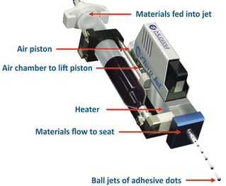
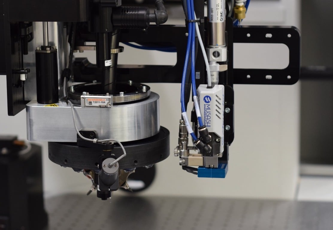
Jet dispensing technologies rarely suffer from any of these disadvantages. Dispensing via a non-contact presence over the location shoots the adhesive fluid at the targeted surface. No touch minimizes tailing, creates tighter pitch, deeper access, and vastly reduces damage possibilities. None of the alternatives have this level of performance. Musashi’s Aero Jet Dispense Pump (see Fig. 1) allowed us to program different sized dots and to jet multiple shots in the same location. A temperature controlling system guarantees optimal viscosity. Once integrated into our Fixed Line BLT software, the jet dispenser delivered exceptional results with tighter process control, significantly better repeatability, and dot consistency. Having now established the advantages and previously outlined the success and repeatability via our proprietary BLT process, we must now overview the practical development work undertaken. Fig. 2. below neatly summarizes aspects of the process. |
|
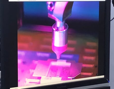 Fig. 2b: The bonder process view camera shows a Vespel pick-up tool designed for high aspect ratio die. The bonder hovered over the GaN die on the waffle pack/Gel-Pak and with vacuum suction on the tool tip, picked up the die and placed it in the targeted location. Fig. 2b: The bonder process view camera shows a Vespel pick-up tool designed for high aspect ratio die. The bonder hovered over the GaN die on the waffle pack/Gel-Pak and with vacuum suction on the tool tip, picked up the die and placed it in the targeted location. |
Since bond line height requirements differ, we modeled our experiment around the most used in RF power applications. Subsequently, we defined the core parameters as (1) surface height measurement repeatability, (2) substrate flatness and roughness, and (3) line consistency. The defining metrics were wet and dry bond line thickness, 100% coverage, a fillet of 70% of the die height, and, of course, zero voids.
In terms of the packaging process:
- A dedicated tool measured substrate surface
- The measurement tool touched the bonding surface to record the reference height.
- The jet dispensed the paste at a height calculated from (2).
- After vacuum pick-up the die was placed/bonded on the paste.
- The die was bonded.
The BLT software required height specification. The bonding surface tool recorded substrate height. With the parameters entered and use of the reference height, the dispenser jetted the Ag sinter paste from a height 2.5 times greater than the intended bond line height. The die was then placed, successfully covering the bottom surface area, simultaneously maintaining the set height. The die was then successfully placed. The process was repeated on 5 test pieces; metrics met in each case. See Fig 3 (below).
|
Fig. 3. |
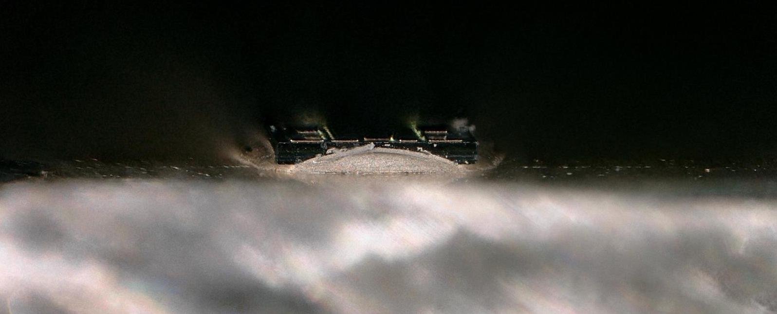 Fig 3b. Epoxy >70% not exceeding the die height.
|
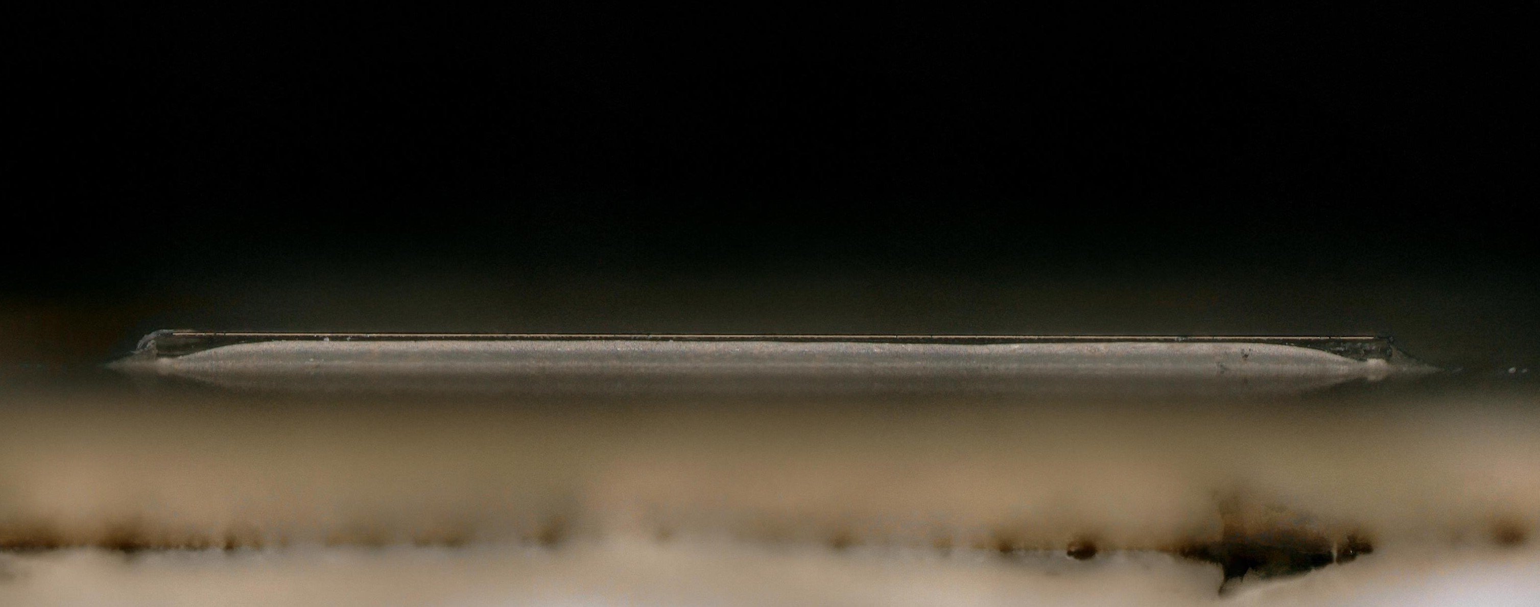
Fig 3c. Epoxy >70% not exceeding the die height. |
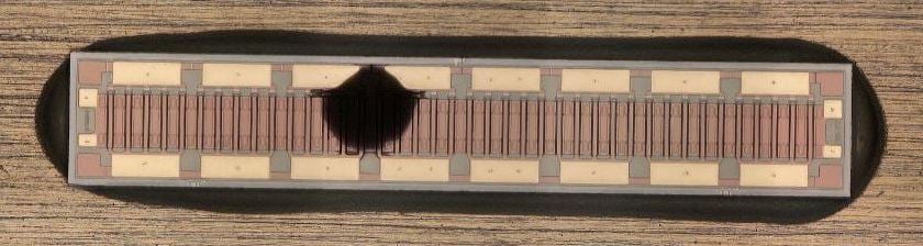 Fig 3a. 100% coverage on die perimeter.
Finally, zero voiding was established using a Sonix HS-1000 C-Mode Scanning Acoustic Microscopy (C-SAM) equipped with 75 MHz transducer. The TAMI region was set from the surface of the coupon up to the GaN die with a 1.882 um step resolution.
Fig. 4 below presents a sample of the void scanning results at 18 different depths (0 um to 32 um). Across the 5 units bonded and a 90 minute interval time between bonding, no voids were present at any of these depths.
Fig. 4.
Void Results
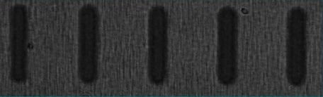
Fig. 4a. 0 um (Surface of GC). |
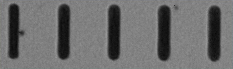
Fig. 4b. 9.412 um cross section |
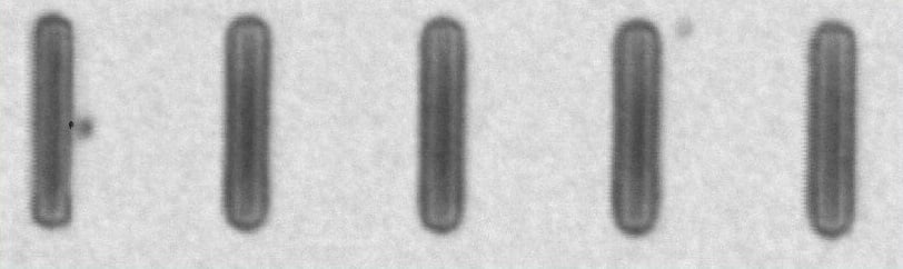
Fig. 4c. 20.706 um cross section. |
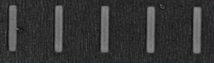
Fig. 4d. 32 um cross section |
Our final blog will elaborate further on the conclusions and implications of our study, the next phases of its technical roadmap, tied in to the wider direction of the ecosystem.
To learn more about pressure-less silver sintering for RF Power Electronics, download our technical article: Energy and Eco-Sustainability using Pressure-less Silver Sintering for RF Power Electronics.