Over the years, microelectronic wire bond process and packaging engineers have debated whether to use ball or wedge bond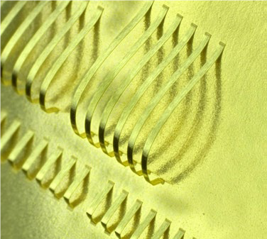 technologies.
This has been especially true with RF designs and fine-pitch packaging. While ball bonding is faster and considered more robust, needs for low profile interconnects or fine pitch in key market segments requires wedge bonding. Another area where wedge bonding typically dominates is where a design requires a running stitch interconnect or die-to-die bonding. These demands have multiplied as advanced LED designs mature.
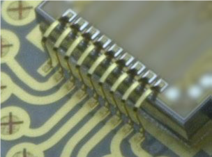
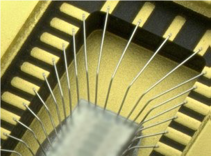
Wedge bonding can be a great solution for performing low profile or fine pitch interconnects and is also well suited for running stitch interconnects—also known as die-to-die bonding and chain bonding—reverse bonding, and ribbon bonding.
There are two basic types of wedge looping processes: forward and reverse. Forward bonding is preferred, where the first bond is made to the die and the second is made to the substrate.
There are two main wire feed angle categories: 45-60°and 90°deep access. Historically, an angle degree change from the 45-60°to 90°required an expensive bond head change. The Palomar 9000 Wedge Bonder supports a simplified and cost-effective approach with a clamp change. This ensures greatest flexibility and scalability while keeping production costs low.
There are several methods to end the wire after the second bond: clamp tear and table tear (better option). For small wires (<.003”/76μm), the clamp can be used to break the wire while machine bonding force is maintained on the second bond. The clamp tear process may offer a slightly higher throughput than the table tear process due to the force maintained on the second bond during the clamp tear motion, but is much more complicated program and may render a more expensive process. Larger wires can require a knife to assist in the wire tear.
If the clamp remains fixed relative to the wire direction and the bonding tool raises off the second bond, this process will tear the wire (table tear). The table tear process has a higher wire feed angle capability due to the back side of tool is as part of the clamp and has the potential to provide slightly more clearance from package obstructions such as a bond shelf or pin grid.
Precision, reliability and consistency should all be reflected in automated wedge bonding. There are MilStd883 guidelines for measurements and testing to ensure quality wedge bonding.
For more information on modern wedge bonding, download our UPDATED Guide to Modern Wedge Bonding eBook.

----
Rebecca Janzon
Global Corporate Communications Director
Palomar Technologies