To begin, let’s start with a brief overview of wedge bonding. Unlike ball bonding, wedge bonding does not have a flame-off action, as there is no ball. And the wire is typically clamped behind the wedge tool instead of above the tool such as for ball bond. With the wire below the tool, the system rotates to position and welds the wire to the surface forming the first bond, the clamp then opens up allowing for the system to draw out the wire path towards the second bond location. It then bonds the second bond and moves to terminate the wire with the clamp closed, leaving behind a small tail of wire below the tool for the bond one of the next wire.
Wedge bonders enable bonding with a large variety of wire and ribbon materials, such as Au, Al, and silver to name a few. With some only needing small changes, depending on wire size and type differences. This makes wedge bonding the bonding of choice in high mix environments.
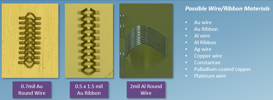
Figure 1: There are a wide range of materials that can be wedge bonded.
Wedge bonders are directional, due to the wedge-to-wedge nature. This means two things: Firstly, wedge bonders need a theta axis to rotate to the orientation of the loop. This allows for bonds to be placed at orientations other than in line with the wire direction. This is called orthogonal bonding. Secondly, wedge bonds are typically longer than they are wide, allowing for tighter pitch while maintaining a good amount of bond area, unless it is ribbon that is being bonded.
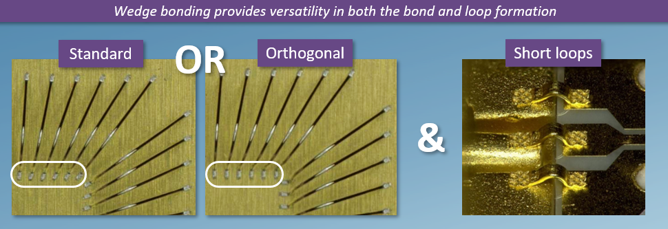
Figure 2: Wedge bonding can create standard or orthogonal bonds and short loops.
Another difference between wedge bonders and ball bonder is that no ball is needed for bonding which allows for lower, shorter loops, depending on tool design. Wedge bonders are capable of deeper access than ball bonders due to not needing to flame off. Ball bonders need a little extra vertical clearance to be able for the EFO wand to clear the part and to have the capillary clear the EFO wand.
With the wedge tool design, wedge bonders are capable of bonding wire closer together with vertically relieved sides. They are also capable of deeper access as they are not limited in vertical range by having to move up to a flame off height with every wire.
Ribbon is unique to wedge bonding due to its shape and cannot be bonded omni-directionally like wire on a ball bonder. It needs to be oriented the right way that can only be provided by specifically designed wedge tools.
Ribbon bonding is preferred in high frequency applications due to the skin effect, due to ribbon’s high surface area to cross sectional area ratio, which means the ribbon will suffer less resistance at higher frequencies. Ribbon bonding is stiffer than round wire and is more resilient to wire sway. And also provides a larger bond area allowing for stronger connections.
Typical Wedge Bonding Applications
A fairly typical application for wedge bonding is aluminum wire. Al wire is unique to wedge bonding due to the oxidation issues at high temperatures. This application uses a 90-degree clamp and is bonded at room temperature. To run Al wire, it’s advised to use a concave wedge tool designed for 2mil Al.
When performing standard bonding, the bond head moves to the location of bond one, rotates it to the orientation of that loop profile. The first bond is welded, then the bond head performs the loop motion, moves to bond two and will make the second weld. The wire is then terminated with a small section of wire under the tool and then the process repeats all over again. All bonds are at the orientation of the wire. As the wires fan out, so do the bonds. This is the most common type of bonding due to the speed penalty seen with orthogonal bonding.
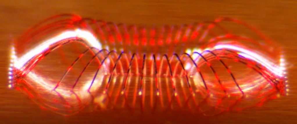
Figure 3: Example of normal wedge bonding.
Orthogonal bonding is very similar to normal bonding except the bond is at a different orientation than the loop orientation. The bonder comes down at one angle, welds the first bond, then rotates before performing the loop mode. This is useful for very tight pitch with fan out wires because it helps to maintain the distance from bond to bond without stepping on the previous bond. It is also used in deep-access packages because it helps to maintain the distance from the wall.
Wedge Bond Looping
There are three primary looping techniques as seen in Figures 4 – 6; these describe the path the bonder makes with the tool to create loops of various shapes and specifications. Although there are some other influences on the final shape of the loop such as air settings and tool design; looping provides the bulk of the loop structure.
The first loop mode is a basic set path with a kick back and is a common choice for its simplicity and robustness. This allows for larger variance in span at the cost of loop height consistency. This is especially useful for development and can handle a large range in bond to bond span.
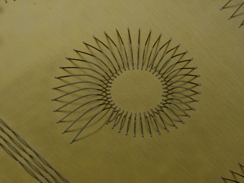
Figure 4: Basic wedge bond.
The second loop technique is similar to the first but introduces clamp actuation during the path. This controls the amount of wire in the loop more finely at certain points. And helps maintain loop consistency and height over a narrower range of spans. This technique is widely used for established processes with limited variation for better loop consistency.
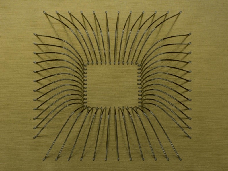
Figure 5: Wedge bond with loop consistency.
The third loop technique is constant wire length. This maintains the length wire agnostic to wire span, at the cost of wire shape and loop height. Most commonly used in RF applications where the amount of wire is more critical despite the span.
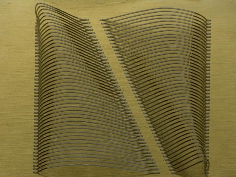
Figure 6: Wedge bonding with constant wire most often used in RF applications.
These loop techniques are able to satisfy the majority loop requirements and specifications for a wide array of applications. They provide easy avenues for development of processes based on the requirements.
To learn more about wedge bonding and how it differs from ball bonding, download these resources:

