Designers of electronic packages require that their components be located very precisely; however, sometimes the positional tolerance of the components cannot be met due to the size tolerances of the components. SST designs and manufactures graphite tooling to meet these needs utilizing cavities to locate the parts (our "Graphite for Microelectronic Thermal Assembly Processes" blog talks more about the 'why' of graphite).
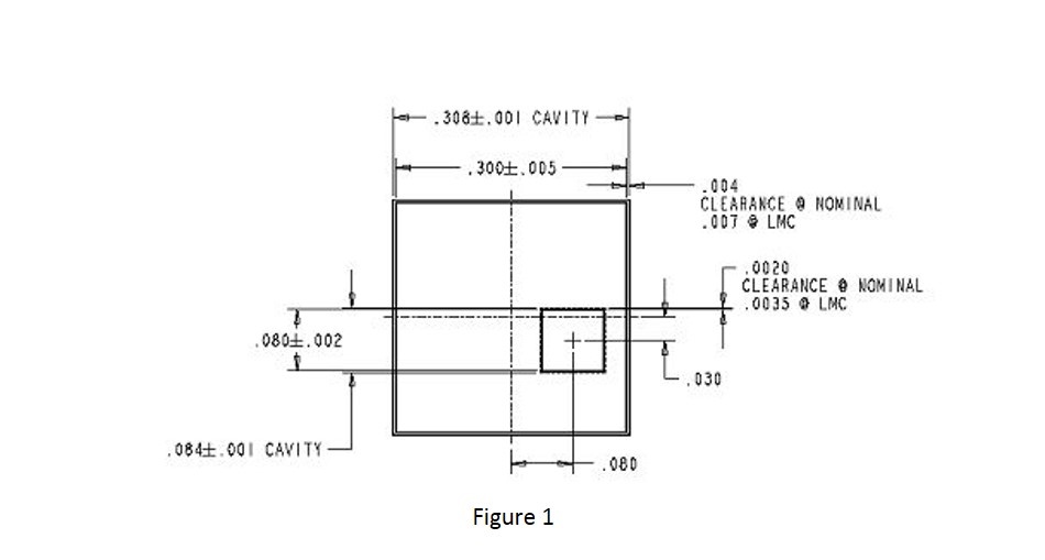
An example is shown below in Figure 1, the parts are shown as squares rather than rectangles to simplify the explanation.

As can be seen, the die has a tolerance of plus/minus 2 mils and the substrate has a tolerance of plus/minus 5 mils. These are typical tolerances for this type of application. The locating cavity must be larger than the components at MMC (maximum material condition) so that with the cavity at its smallest and the die at the largest, it will still have some clearance in the cavity in order to place the part in the cavity.
When the parts are at LMC (least material condition), the clearance in the cavities is the greatest. In this example, the clearance for the substrate at LMC of .007 is per-side, so total clearance is .014. Likewise, the die has a clearance of .0035 per-side, total clearance being .007. So if the substrate and die are shoved to opposite corners, the offset would be greatest at .014 plus .007 = .021”. At worst-case, the relationship of the die to the substrate could be plus/minus .0105” (.021/2), meaning that the .030 dimension could be .0195 to .0405 or .030 +/-.0105. If the parts were pushed into the same corner, the offset would be one-half at +/-.00525.
In order to reduce this locational inaccuracy, the part tolerances should be reduced if possible. Also possible would be to allow less clearance in the cavities, which makes part loading more difficult if the parts are near their maximum allowable sizes. Another possible alternative is for a tighter machining tolerance of the cavities.
The bottom line is this: the positional tolerance cannot be less than the combined size tolerances, unless… Please stay tuned for the next blog in this series for SST’s solution to this problem.
Download these resources for more informations:
| Graphite Tooling | Process Development | Model 5100 |
---
Dan Ross
Mechanical Design Engineer
SST International