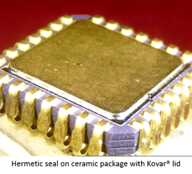
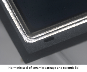
As we continue this series on the Methods of Testing Device Hermeticity According to MIL-STD-883, we will start looking at the various methods for determining the leak rate of microelectronic devices with internal cavities, in compliance with MIL-STD-883J. Part 2 of this series will be focused on Trace Gas (He).
As covered in the first blog of this series, the review standard provides for eight (8) methods of verifying device hermeticity given certain conditions. These methods are:
- Trace Gas (He)
- Radioisotope (Kr85)
- Perfluorocarbon Gross Leak
- Optical
- Penetrant Dye Gross Leak
- Weight Gain Gross Leak
- Radioisotope (Kr85) (Thermal Leak Test)
- Cumulative Helium Leak Detection (CHLD)
The first method in the list is Trace Gas (He) which is commonly referred to as Helium leak testing. This method is widely used for testing the fine leak (usually any leak <EEx10-7 atm cc3/s (He)) status of a sealed cavity device. The process requires a method for introducing Helium to the device and a mechanism to measure to subsequent leakage of the helium from the leaking device.
The equipment required for this testing is a pressurization chamber for the bombing of the devices to be tested and Helium Mass Spectrometer. The mass spectrometer should have a vacuum chamber that is practically small enough to reduce the overall volume while still accommodating the parts to be tested. The parts are pressurized as prescribed and then put into the mass spectrometer for leak measurement based on the amount of helium that is being released by the test device.
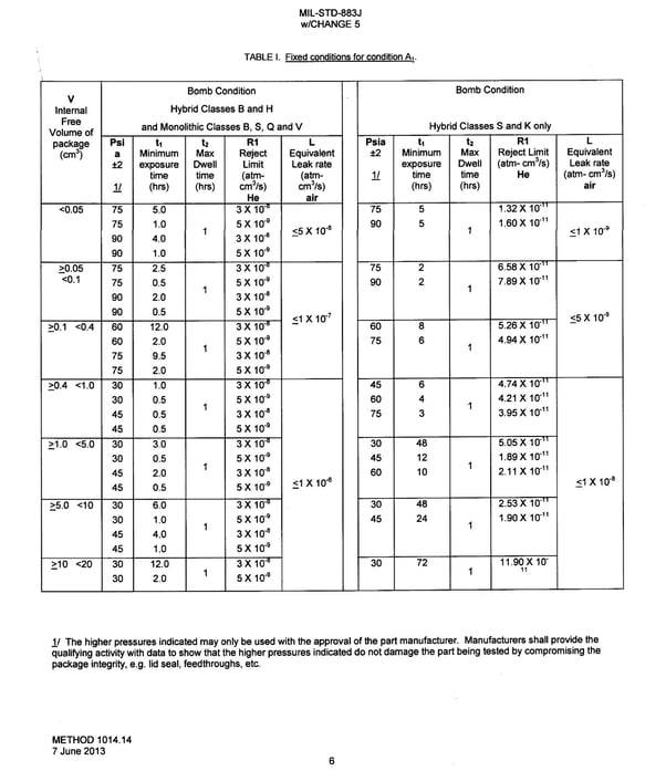
There are two (2) test methods used for helium leak testing. The first is the fixed method (Test Condition A1) where devices must first be pressurized, or bombed, with helium for a prescribed period of time, relative to the internal free volume of the device. Depending on the internal volume and type of device, the bomb pressure could be as high as 90 pounds per inch2 (PSIA) and for as long as seventy two (72) hours. MIL-STD-883J provides a table showing these conditions. This same table also shows the possible failure limits ranging from 3 x 10⁻⁸ atm cc3/s (He) to 11.9 x 10⁻¹¹ atm cc3/s (He), depending on the device type and volume.
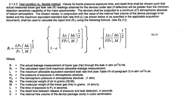
The second is the flexible method (Test Condition A2) where once again the device must be bombed as in the fixed method, except that the dwell time must be calculated based on the internal volume of the device and using a minimum of two (2) atmospheres absolute (He) . The failure limits for this method range from 1 X 10⁻⁷ to 1 X 10⁻⁹ atm cc3/s (air), which would require calculating the true leak rate from the measured Helium leak rate of the test instrument. This is the Howell-Mann equation.

This test method has been used for many years and is generally accepted however as device volumes get smaller this method is less reliable. Additionally surface sorption of helium can result is false test failures resulting in the loss of valuable devices.
To be considered hermetic by Mil Spec the sealed package must pass both the fine helium leak test and a subsequent gross leak (also called bubble) test in this order.


Watch for the next blog in this series as we continue to cover all eight (8) methods of verifying device hermeticity.
References
1. MIL-STD-883J
w/CHANGE 5
Method 1014.14
7 June 2013
United States Department of Defense, Defense Logistics Agency
Links
1. Defense Logistics Agency, (DLA) History
| Model 1200 | Model 3130 | Model 5100 |
| Model 3150 | Model 3180 & 3190 | Model 3250 |
---
Bruce Wilson
Regional Sales Manager
SST International