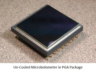
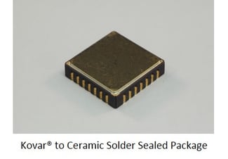
In this series we will look at the various methods for determining the leak rate of microelectronic devices with internal cavities. Much of this information will be summarized from MIL-STD-883J, Method 1014.4, 7 June 2013. This standard is administered by the United States Department of Defense, Defense Logistics Agency and is approved for use by all Departments and Agencies of the Department of Defense. The Military, and Aerospace sectors have used these standards since the introduction of the base standard, MIL-STD-883, May 1, 1968. Over time these standards have also become a normal part of many other microelectronic sectors such as telecommunications and medical device manufacturers. The standard has been updated 10 times, over the years, and there is currently a notice of change to MIL-STD-883K, which has not yet been released. For this series we will stay with the current standard.
The standard provides for eight (8) methods for verifying device hermeticity given certain conditions. These methods are:
1. Trace Gas (He)
2. Radioisotope (Kr85)
3. Perfluorocarbon Gross Leak
4. Optical
5. Penetrant Dye Gross Leak
6. Weight Gain Gross Leak
7. Radioisotope (Kr85) (Thermal Leak Test)
8. Cumulative Helium Leak Detection (CHLD)
In future postings we will also explore other methods of hermeticity testing such as electrical resistance, integrated pressure sensors, FTIR spectroscopy and Q measurement.
Each of these methods are useful under specific conditions and many times are to be used in conjunction with one another. These methods also each have their own advantages, disadvantages and limitations. As microelectronic device cavity volumes get smaller and smaller these issues become more pronounced. Determining which method to use has filled volumes, and volumes more could still be written about them. This series will try to help define each of these methods so that an informed decision can be made in determining the appropriate test method for a given device.
Before trying to understand test methods we should first define Hermetic(ity). For the purpose of this investigation we will use the following definition:
Hermetic [hur-met-ik] Adjective
1. Sealed so as to be airtight.
2. Isolated from outside atmospheric influence.
Even after defining hermetic it must be understood that, in regards to microelectronics, the level of hermeticity must be defined. This is referred to as a leak rate. The leak rate is usually defined as a standard leak rate, atm cc3/s (air) or a measured leak rate of atm cc3/s (medium used). These rates are then further defined, by the industry, as either a gross leak or a fine leak. The actual boundary between gross leak and fine leak is many times determined by the test methods used. However it is generally accepted that a gross leak is any leak >EEx10- 6 atm cc3/s (He). A fine leak is usually any leak <EEx10-7 atm cc3/s (He). What must be kept in mind is that at some level all things leak it is really a matter of at what rate will the internal device atmosphere be exchanged for the outside atmosphere.
References
1. MIL-STD-883J
w/CHANGE 5
Method 1014.14
7 June 2013
United States Department of Defense, Defense Logistics Agency
Links
Defense Logistics Agency, (DLA) History
| Model 3250 Data Sheet | Model 3180-3190 Data Sheet | Model 1200 Data Sheet |
---
Bruce Wilson
Director of Sales
SST International