Flip chip processes have been around for more than 40 years. Since then, thousands of applications have taken advantage of the size and cost benefits enabled by the flip chip assembly method.
Flip chip is a method used for components or devices that can be bonded directly onto a substrate, board or carrier face-down. The connection is made through conductive bumps placed on the surface of the die.
Flip chip bumping is a vital step to the process. The bump provides the necessary electrical connection between the die and the substrate. This connection provides thermal conduction through the two materials as well as acts as a "spacer" to provide mechanical support and electrical conductivity.
|
At a top level, flip chip involves three critical steps:
|
 |
Common Flip Chip Bumping Processes
Solder Bump
The solder areas on the chip bonds are defined with Under Bump Metallization (UBM). After the solder is deposited over the UBM, the wafer is sawn into bumped die. The bumped die are then ready to be placed on the substrate pads for attachment process.
Plated Bump
Nickel-gold bumps are formed on the wafer by electroless nickel plating. After the appropriate thickness of nickel is applied, an immersion gold is added for protection. The wafer is then sawn into bumped die before being placed on the substrate pads and the interconnection made.
Stud Bump Stud (or ball) bumping is a modification of a wire bond process. The optimization of any gold flip chip process is achieved by optimizing the bump shape. New bump formation techniques have been developed that can create a gold bump without the traditional tail. This bumping process was designed specifically for a thermocompression or thermosonic bonding process. This bump shape directs the compression forces to assist in the formation of an intermetallic bond.
By focusing the applied energy down to a smaller surface area, the other bond parameters (heat, force, and ultrasonics) can be reduced. As this bump continues to be compressed and deformed, the surface area in contact will grow to increase the conductive area. The wafer can then be sawn into a bumped die before being placed on the substrate pads and the interconnection made. The gold stud bump process can be performed on a single die, as well as a whole wafer.
Adhesive Bump
Conductive adhesive is stenciled on the UBM to form bumps on the wafer bond pads and is then cured. The wafer is then sawn into a bumped die before being placed on the substrate pads for attachment process.
Flip Chip Advantages
There are several advantages to the flip chip assembly process, including cost, component performance/reliability and design flexibility. By flipping the device directly to the external circuitry, bond wires can be removed from the equation completely. This can reduce package sizes and weights significantly. Smaller package designs typically translate to reduced production costs.
Flip chip process—such as direct chip attach (DCA)—can eliminate the need for wire bonds. Wire bonding can be considered a peripheral technology for flip chip applications due to the number of external connections to the available surface area along the external peripheral of the die. More connections means larger die sizes. Eliminating the bond wires also results in the capacitance (the ratio of charge to potential on an electrically charged, isolated conductor) and inductance (a measure of the reaction of electrical components to changes in current flow by creating a magnetic field and inducing a voltage) of the electrical connections to greatly reduce which creates high-speed electrical connections.

And lastly, because flip chips are bonded directly onto other circuitry and can be filled with a robust, non-conductive adhesive (underfill), flip chips are ideal for end-use applications used in harsh climates—commonly for industrial or military industries.
Learn more:
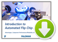
Introduction to Automated
Flip Chip Assembly
|
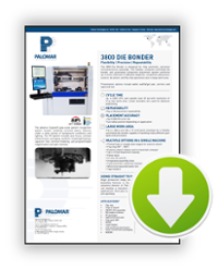
3800 Die Bonder Data Sheet
|
Royce Instruments
|
----
Sarah Kinzli
Sales Applications Engineer
Royce Instruments, Inc.
Jessica Sylvester
Marketing Communications Manager
Palomar Technologies, Inc.
Palomar Technologies would like to thank the Royce Instruments, Inc. team for a collaborative guest blog. Together, Palomar and Royce offer customers a complete view of the reliability and quality of wire bond and die attach applications.
For more information on the Royce Instruments, Inc. product line of US designed and manufactured bond testers and die sorters, please contact Sarah Kinzli, Sales Applications Engineer, at skinzli@royceinstruments.com or (707)255-9078 x142; or visit Royce online at www.royceinstruments.com