Wire bond interconnects have traditionally been considered "forward" bonded wires. Forward bonding refers to bonding from an integrated circuit/component down (or up) to a substrate/package. Most first-level interconnects have been made in this way until recently. MIL-STD-883 does not allow tool impressions on an active device like an integrated circuit, so this has been the only method available until recently.
Today, automatic gold ball bonders can create both traditional wire bonds and ball bumps. With this refined capability, we can place a flat-topped bump on an active integrated circuit (IC) pad, flame off as normal, and then reverse bond from the substrate, package, or even another active device back to the flat topped ball bump. This is done with standard Be-doped wire, standard off-the-shelf capillaries, and an all-in-one single wire bond program.
|
|
 |
|
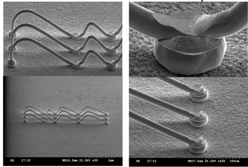
We call this methodology Stand-Off Stitch (SOS) bonding. It is not limited to just reverse bonding or even chip-to-chip bonding, but works equally as well with forward bonding or in a running chain bond. It can be as simple as clicking a box in a pull down menu when programming the device to be bonded. SOS bonding places a ball at each end of the wire, much like security bonds of the past. However, the second bond ball is under the second bond stitch, not on top. |
 |
 |
Learn more about Wire Bond Pull and Ball Shear Testing from Royce Instruments. |
Using the SOS method for wire bonding has many advantages, including the enabling of multiple bonding methods. With the resultant wire having a ball on each end, we reduce to near zero the opportunity for bond adhesion failure which is one of the worst possible mechanism failures for a wire bond. Reverse, forward, chip to chip, and chain bonding all benefit. The resulting wire pull destructive tests will yield almost exclusively mid-span breaks or breaks in the Heat Affected Zone (HAZ) above the ball. Pull strengths quickly approach the tensile strength of the wire. This is an incredibly important outcome for wire bonding challenges!
 Another benefit of SOS bonding is that it meets the requirement for reverse bonding to integrated circuits in order to remain MIL-STD-883 compliant. Since there is a flat top ball on the integrated circuit pad, when the bonder stitches off its second bond it does not disturb bond pad metallization (whether the IC bond pad is passivated or not). It is not required for reverse bonding to a package or pin, but in general it is recommended. Wires can also be made much shorter as they do not require the large loop above the ball as is needed when performing traditional forward bonding.
Additionally, the SOS methodology enables IC-to-IC bonding. For the first time ever, we can now bond a single wire between two integrated circuits. In this case the wire is neither forward or reverse bonded, but the direction can be chosen either way to allow the best possible outcome (i.e. loop shape, loop height, destructive test strengths, etc.) given the bond heights of the two ICs. This methodology allows the two integrated circuits to be placed very close to one another which helps shrink the overall package size and reduces wire count, thus improving package reliability.
 Finally, running stitch "chain bonding" can be performed forward, reverse, chip to chip, and with or without SOS methods. In general, if the bonding wire is less than 1.5 mils (~38 microns), we need to evoke the SOS method so that we do not leave tool impressions on active circuitry.
In review, the combination of SOS bonding with forward, reverse, IC-to-IC, and running stitch chain bonding allows the microelectronic packaging engineer many options for improved performance, package shrink, and increased product reliability.
----
Bradley Benton
Regional Account Manager, Western Americas
Palomar Technologies, Inc.