When it comes to microelectronics assembly, there are many challenges and solutions. One of the most critical differences between a manual or semi-automatic bonder and a fully automatic bonder is the ability to find and identify specific features, fiducials, or components on the parts. This is critical for accurate placement of die as well as wire bonds.
Auto Correlation
Many manufacturers of automatic systems utilize auto correlation for locating and comparing “taught” references to “found” references. Auto correlation, for the most part, is comparing pixel to pixel from the taught image to determine if the found image is within an acceptable level in order to give the system the “go ahead” to proceed with the next step, whether that might be placing a die or a wire bond.
Some of the challenges with auto correlation is that it is based on teaching repeatable and predictable images. This requires that the images you teach are a good representation of all the parts yet to come. For years, Palomar has used tools such as programmable lighting and auto focus to try to ensure that the auto correlation has the best opportunity to find the taught location/image on every subsequent part. We also use Cognex®, a world leader in vision systems, as the “eyes” of our system.
Even with the best tools implemented, there are still challenges to the auto correlation approach to certain components/packages. Components such as borderless capacitors, feedthrough pins, and moly tabs are not well defined and can vary greatly from part to part. With auto correlation you either have to have multiple alternate references that represent a spectrum of part types, or your threshold set so low that you have “false finds”. This will cause parts/wires to be placed in the wrong locations. In many cases, customers would rather manually reference the parts than risk placing the part/wire incorrectly.
Dealing With Challenges of Auto Correlation
At Palomar, we recognized this issue as an area that needed improvement for customers who were dealing with these challenges and developed an entirely new approach for vision capture. It is called VisionPilot® with Radar Referencing®, and is now available on all of our die and wire bond systems.
 |
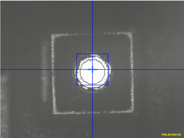 |
VisionPilot takes a completely different approach in that it is looking for a shape instead of a pixel-to-pixel comparison. The shapes are created from the model image. The shapes from the model image are then used to find the model. Since you are looking for a shape, there is no confusion with probe marks, scratches, or other issues on the surface. It is also less sensitive to light and part variation. Parts that were once unfindable are now easily taught and found.
For the taught image, instead of using a “golden part” you can use a synthetic model creator tool for teaching the reference. This feature is useful in creating the perfect reference instead of trying to find a golden part to match future references.
There is also an “active feedback” capability to help process engineers and operators quickly evaluate find performance.
We have already implemented VisionPilot in various customer applications where they were struggling with teaching a model that would work with auto correlation. In all of these cases, we have seen dramatic improvements in the capture rates--some examples going from less than 10% capture to over 90% capture.
If you are struggling with pattern recognition issues, please contact us to see if VisionPilot could be a solution. VisionPilot is offered on new systems and can be retrofitted to certain versions of our existing systems.
Download VisionPilot and other die and wire bond resources here:
| VisionPilot Data Sheet | 3880 Die Bonder | 8000i Wire Bonder |
 |
 |
 |
----
Dale Perry
Eastern Americas Regional Account Manager
Palomar Technologies, Inc.