We have all been there—your wire bonder is giving you that steady working “hum” and the product your customer needs is nearing on-time completion. All is seemingly well, until…flame off! “Okay,” you tell yourself, “No big deal; just a freak thing. Rethread the wire and try again.” Yikes—it happened again! You assume it’s not major, but with the product delivery deadline looming, you need to quickly diagnose where the problem lies. The first two big questions: Is it the part? Or has something happened to my bonder?
As innate problem solvers, process engineers may all have a different path to resolving this issue. You may have a “golden part” that you run too quickly, determining whether there is some type of issue with the suspect part. If your troubleshooting path directs you towards the wire bonder, you have many diagnostic tools, often including the machine itself. If the problem remains unresolved, you also have external tools to check the critical criteria for a good ball bond, thermocouples to check the heat, load cells to monitor force and, wait a minute… how am I going to check the ultrasonics?
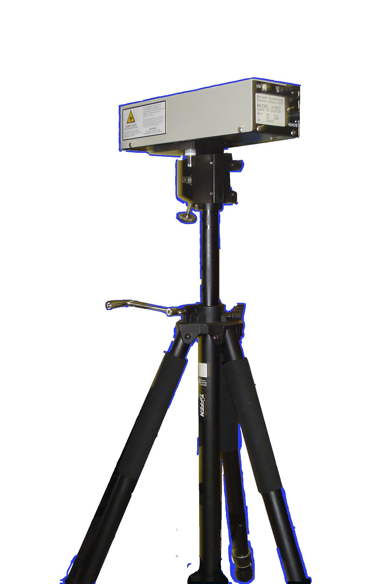
Measuring micro-inches of a movement in a bonding transducer is a big challenge. One solution for the measurement of free air micro excursion is with a 2100C Laser Interferometer, which provides the capability of measuring frequencies in a range of 40khz – 160khz.
The 2100C Laser Interferometer provides a non-contact method to check the performance of the ultrasonic system of a wire bonder. The 2100C’s highly specialized electronic system processes feedback signals from the laser and digitally displays the results in
millionths of an inch, providing an accurate measure of the ultrasonic performance.
So, How Does It Work?
Using laser interferometer technology, actual ultrasonic excursions are precisely measured by counting interference fringes. A portion of the He-Ne (λ=24.9μ inches) laser beam is focused onto the front of the oscillating transducer horn. Laser light reflected back from the transducer generates interference fringes that are received at a PIN photodiode. Interference fringes produce a pulse, which is amplified and transmitted to the sampling electronics. Since the transducer displacement is proportional to the fringes generated per second, a statistical process of averaging the pulses results in a display resolution of 1 micro-inch. The sampling electronics are based on the known vibration frequency of the ultrasonic system. Since the measurement takes place at the transducer horn, the performance of the entire ultrasonic system is accurately measured.
No “tool kit” would be complete without some method of being able to qualify the capability of the ultrasonic system. After all, this is the “heart” of the wire bonder. The 2100C Interferometer is based on proven technology that has been in use for over 30 years, providing peace of mind for both routine bonder maintenance and when production timelines come down to the wire.
----
Dale Perry
Regional Sales Manager, Eastern North America
Palomar Technologies
