The RF power amplifier market is expected to increase substantially in the next five years, primarily as a result of the 5G rollout which depends heavily on new power amplifier assemblies in the base stations. The estimated CAGR for the general RF power amplifier market is 5-6% from 2020-20251. This anticipated demand translates into a subsequent necessity for RF power amplifier manufacturers to increase their volume of production. Yet, a simple ramp up will be insufficient as with this growth in volume also comes new challenges and processes to develop and refine. The market suppliers must simultaneously churn out considerably more devices while dealing with design, material, and process faults. In addition, these companies need also maintain the integrity of their assemblies as they represent the pillars for the foundation of a new commercial initiatives and therefore require high reliability and performance in order to convince the public of their acclaimed abilities.

The overall market for RF Power Amplifiers.
In order to ensure the key metrics for RF Power transistors are properly maintained in an automated assembly environment, process control steps are required. When reviewing the options for monitoring and controlling process variations, there are two separate approaches; passive and active control techniques.
Passive control steps usually consist of changes to the base process that reduce variation or improve overall build quality. These alterations can be in the form of using different hardware or substituting one assembly material for another. One such example would be switching from a Time Pressure dispense unit to a Jetting Pump for dispensing adhesive. The Jetting Pump is expected to have greater volume control and be less sensitive to surface irregularities, but will change the assembly sequence for every build.
In regards to specific control steps available for RF power amplifier transistors, regulating dispense, bond line consistency, solder quality, and die placement are important. The tools available for dispense control include both passive and active control steps. For passive, there are various dispensing options that can be outfitted to a Palomar die bonder. A standard time pressure system is the simplest but does not offer much in the realm of control. An auger pump uses a volume-controlled method for dispensing but is still susceptible to surface variations and fluctuations in fluid temperature. A jetting pump has both temperature and volume control systems with its onboard heater block and precise valve controlled adhesive chamber. The jetting pump is also not susceptible to any valleys or peaks found on a surface which would otherwise cause a break in the pattern for other dispense systems. The cause for inconsistent dispense is due to the capillary action and surface tension that helps pull the adhesive from the needle for time pressure and auger solutions; when the adhesive loses contact with the surface, it will build up at the needle instead of being deposited. Since the jetting unit can dispense from as high as 150mils, because of its mechanism which is to rapidly eject small balls of adhesive onto a substrate, the surface quality of the package makes little difference to the overall volume control and pattern consistency for a jetting pump solution.
Active control steps include a separate process statement to visually check the dispense pattern on the surface of the substrate before die placement. This step would verify volume control and pattern quality but would add extra cycle time. The active step could be amortized across several assemblies if it is set to execute only once every x runs, which is not an option for passive control steps. The flexibility of active control steps makes them an attractive option during the maturation of a new process or device.
Various hot rail handler options are examples of passive controls used to ensure proper temperature for regulating solder quality. The software used to run the handler is an example of an active control.
Active control tools for regulating dispense consist primarily of vision-based checking to verify dispense volume and pattern uniformity. These steps are possible with the usage of the Palomar VisionPilot® tools in the Palomar 3880-II Die Bonder. These pattern recognition algorithms alert the operator or halt the program if the actual dispense deviates too much from the expected pattern. For instance, if a clean star pattern was the intention, but one or two of the ‘legs’ of the star are missing or have gaps, then the vision system picks this up and takes action. In addition, the bonder also sets limits on overall pattern width/volume and can fail adhesive deposits that have too much or too little volume. These checks are placed anywhere within the program and at any desired frequency. It is also possible to create a ‘diagnostic’ dispense step to execute every ‘x’ builds where a more complex (or simple) pattern can be used to verify dispense/adhesive quality.
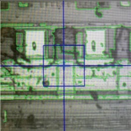 VisionPilot® Radar referencing of a damaged die surface.
When trying to maintain bond line consistency, the primary issues to deal with are adhesive irregularities and surface variations. As controlling adhesive dispensing was just discussed, surface quality will be the topic of the discussion for the challenges of bond line repeatability. Conventional placement techniques rely on a ‘force controlled’ approach – that is the pick and place operation is driven by applying a set amount of force once contact is made with a surface. When placing a die into adhesive on a rough surface, that contact point and the required force can vary, especially if there are any high points in the package relative to the average surface height. Thus, when aiming for a set bond line thickness, being able to drive to specific heights, independent of force is more important. This poses an issue however if the taught surface height is not repeatable – from varying overall package thickness, for instance. Even a few microns difference can impact bond line consistency, thus it is advised to first measure the height of the surface with micron level accuracy. On the die bonder this is done through touchdown or with a contactless method such as a confocal sensor. This sensor is extremely fast and repeatable, allowing for multiple measurements quite quickly for the most accurate understanding of the package surface. This passive method can be employed to ensure bond line repeatability for every assembly. The same confocal sensor can even be used to check the die height after placement for verifying bond line thickness and tilt of the die in respect to the surface measurements from earlier.
For preventing component damage in general, or even simply just monitoring die placement, the die bonder vision system can be used to great effect. Often a simple active process control step consisting of a single reference can be enough to prevent repeated misplacement or consecutive component damage. This can be achieved by using a unique feature of the VisionPilot® referencing system, referred to as the ability to ‘score clutter’. Essentially, the pattern recognition algorithms can use excess data (i.e. clutter) which comes from debris, chips, and scratches, to lower the given ‘score’ for a reference. This allows rejection of die based on damage or cleanliness. Using this technique before beginning any assembly allows for die sorting during the actual build process to prevent any waste of material. It is also possible to use this same ‘chip damage check’ after placement to avoid any instances where damage was done through any debris collected on the vacuum tool – a situation, where when left unchecked could result in consecutive device destruction until noticed much later down the line. This control step can also simultaneously check for die placement repeatability in terms of X, Y, and Theta, further adding to the complete control options available.
Conclusion
The importance of process control in markets that require both high demand and high reliability cannot be understated. These steps not only ensure the required device performance but also significantly accelerate the learning and maturing process for the design and assembly sequence. In the early stages of a product, it is wise and likely necessary to implement several high frequency active process control measures. As time goes on, transitioning to more passive control schemes and finally discovering solutions to reduce the need for process control will be the goal. Process control and throughput will always be a delicate balance in any process, but understanding the tools on hand and using them intelligently and collectively will certainly guarantee an optimal path to maximum production volume without sacrificing quality or performance.
To learn more about balancing throughput and process control, read our technical article: Balancing Throughput and Process Control for RF Power Amplifiers.
Download these resources for more information:
 |
 |
| 3880-II Die Bonder Brochure | Energy and Eco-Sustainability using Pressure-Less Silver Sintering for RF Power Electronics |
----
Kyle Schaefer
Palomar Product Marketing Manager
Palomar Technologies, Inc.